FANUC Text-to-Trajectory Writing Robot
A Python generator that turns typed text into a FANUC motion program, and the industrial robot that wrote it out in ink.
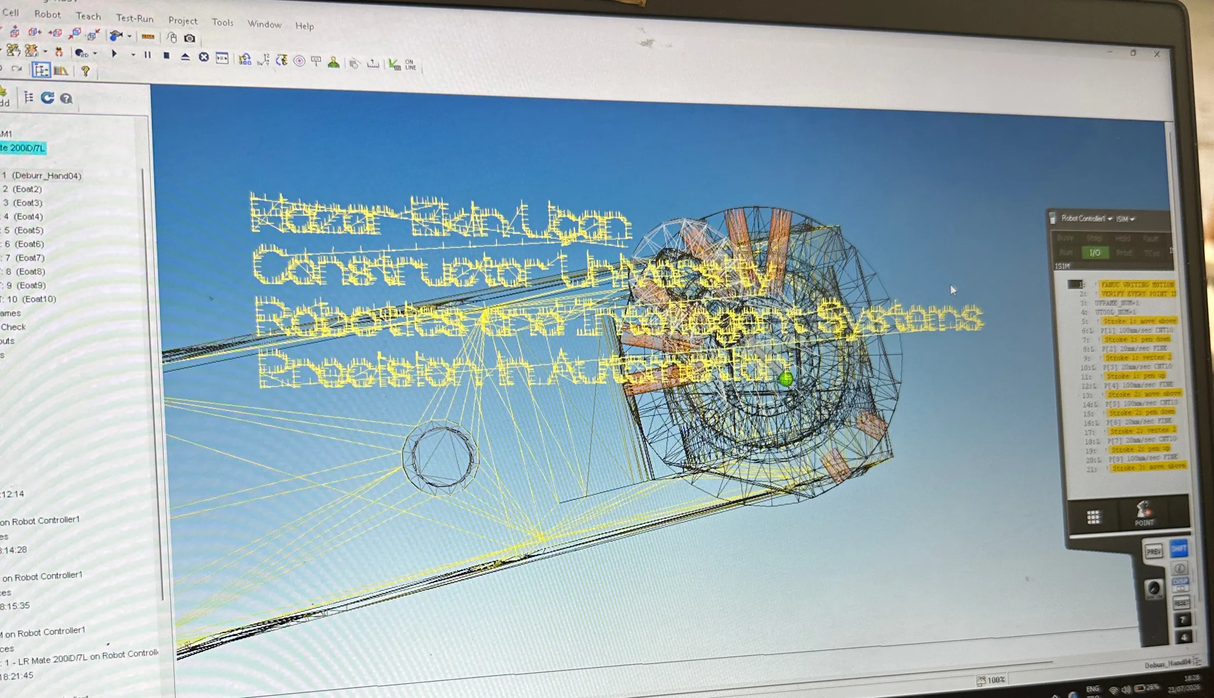
What it is An industrial robot that writes typed text with a pen, running a program I generated instead of teaching it point by point.
What I built A single Python file, a pen gripper with a spring in it, and the calibration that made the two work together.
My role
I wrote the generator: the stroke font, the layout and automatic fitting, the point builder and the three exporters. I designed and built the pen gripper, then redesigned it around a spring when the first version would not draw a consistent line. I set up the cell in RoboGuide, operated the teach pendant, calibrated the tool and the writing plane, and troubleshot the result on the physical robot. My supervisor's reference letter records the same scope.
01
Teaching a robot to write without teaching every point
A short phrase is hundreds of robot positions. I did not want to record them by hand.
In the last two weeks of my internship there was a FANUC 200iD/7L in the workshop with no customer project on it. I had spent the previous weeks on palletizing cells, where the robot moves a bag from one place to another. I wanted to build one complete system instead of practising isolated commands, so I decided to make the robot write.
The usual way to do that is to jog the robot to each point and record it. A short phrase is hundreds of positions, so teaching them by hand was never going to work. I wanted a repeatable path from the text I type to a motion program the controller can run.
Writing is also less forgiving than pick and place. The pen tip has to stay near a plane across the whole sheet. The contact has to be firm enough to leave a line and light enough not to bend anything. Hundreds of small moves have to run in the right order. Any of those is where a coordinate system error shows up.
- Paper Fits A4 landscape at 297 × 210 mm, or the text shrinks until it does
- Characters A-Z, a-z, 0-9, punctuation, and the Turkish letters ç ğ ı İ ö ş ü
- Safety No coordinate outside the configured envelope ever reaches the robot
- Workflow Output has to load through the normal FANUC program workflow
- Orientation The Cartesian CONFIG and W/P/R come from a point validated on the real robot, not from a guess
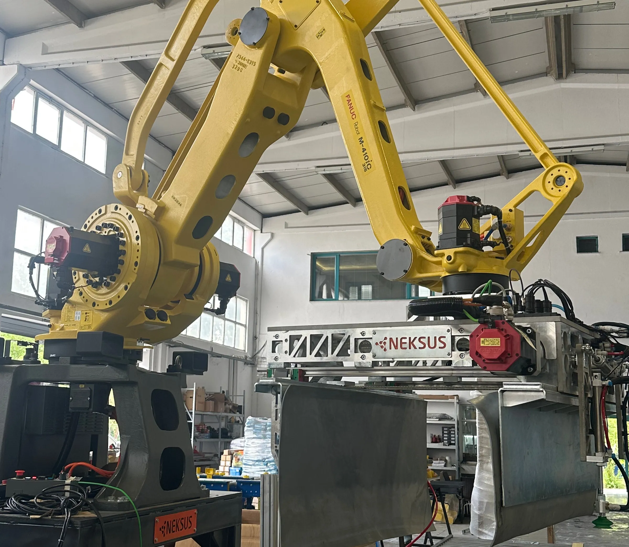
02
Generate the program, don't teach the points
Text goes in, a motion program comes out, and an SVG preview shows the path before the robot runs it.
The generator is one Python file with no third-party dependencies. That was deliberate: it had to run on a workshop laptop without anyone installing anything.
The font is the part people do not expect. Each character is a list of polylines
in a unit box. There are no outlines to fill, because the pen draws one stroke at
a time. In that box y = 0 is the cap height, y = 1 is the baseline, and
descenders reach 1.30. A glyph maps straight onto the segments where the pen is
down.
The Turkish characters are composed at runtime. ç is c plus a cedilla stroke,
ğ is g plus a breve, ü is u plus a diaeresis. To add a language I add
accent functions instead of redrawing an alphabet.
Diagram: generation pipeline
- 01 Input Text A-Z, a-z, 0-9, Turkish letters, punctuation
- 02 Font Stroke polylines unit box, y=0 cap height, y=1 baseline
- 03 Layout Millimetre strokes cursor walk, spacing, line breaks
- 04 Auto-fit Largest height that fits binary search, refuses below 3 mm
- 05 Points Ordered robot points TRAVEL · PEN_DOWN · DRAW · PEN_UP
- 06 Check Envelope validation out of bounds raises, never clamps
Outputs
- writing_preview.svg checked before anything reaches the robot
- writing_points.csv point list with motion type and speed
- ISIM.LS /PROG /ATTR /APPL /MN /POS /END
Three decisions in that pipeline mattered more than the rest.
The first is automatic fitting. If the text does not fit the paper, the generator searches for the largest letter height that does, scaling character and word spacing by the same ratio so the proportions hold. It only ever shrinks the text. Below 3 mm it stops and refuses, because the pen cannot resolve letters that small.
fanuc_writer_ls.py · fit_text_to_paper()
low = minimum_height_mm
high = original_height

# Binary search for the largest height that fits.
for _ in range(50):
  middle = (low + high) / 2.0
  candidate = scaled_config(middle)
  if fits_paper(layout_text(candidate), candidate):
      low = middle
  else:
      high = middle

return scaled_config(low * 0.999)
Fifty iterations of bisection, then just under the last height that fit.
The second is the termination type on each point. This is what decides whether the line looks clean.
Diagram: pen motion state machine
- Travel Move above the next stroke's first point 100 mm/sec · CNT10
- Pen down Descend to the writing plane 20 mm/sec · FINE
- Draw Every vertex of the stroke, in order 20 mm/sec · CNT10
- Pen up Lift clear before the next stroke 100 mm/sec · FINE
The points where the pen goes down and comes up are emitted as FINE. Those are
the two moments the tip has to arrive exactly where it was told. Every vertex in
between is CNT10, so the controller blends the corners instead of stopping at
each one. With FINE everywhere the robot stutters through every character. With
CNT10 everywhere the pen rounds off the start of each stroke.
fanuc_writer_ls.py · export_fanuc_ls()
for point in points:
  termination = (
      "FINE"
      if point.motion_type in {"PEN_DOWN", "PEN_UP"}
      else "CNT10"
  )
  motion_instructions.append(
      f"L P[{point.number}] {point.speed_mm_sec}mm/sec "
      f"{termination} ;"
)![A laptop screen showing the RoboGuide 3D view beside the teach pendant program list, where lines read Stroke 18 vertex 3, P[111] 20mm/sec CNT10, Stroke 18 pen up and P[119] 100mm/sec FINE.](/_astro/roboguide-program.CeFkcLep_Z251Myz.webp)
The third is what happens when something is wrong. Every point is checked against the configured bounds before any file is written. A coordinate outside the envelope raises an error instead of being quietly clamped. A program that fails to generate costs a minute. A program that silently moves a point to the edge of the paper costs whatever the robot hits.
fanuc_writer_ls.py · validate_xyz()
if not all(math.isfinite(value) for value in (x, y, z)):
  raise ValueError(f"Non-finite coordinate: {(x, y, z)}")
if not (config.min_x_mm <= x <= config.max_x_mm):
  raise ValueError(f"X out of bounds: {x:.3f} mm")
For the same reason, the CONFIG string and the tool orientation are parameters with a warning in the docstring. I did not bake values into the file. They have to be copied from a validated point on the exact robot, and a default that looks plausible would be worse than no default at all.
03
A spring in the gripper
The path was right and the line still came out faint. The fix turned out to be mechanical.
The coordinate system was the hard part of the software, and it took longer than I expected. Scale, origin, writing plane and stroke ordering all have to agree, and if any one of them is off the characters come out sheared, mirrored or in the wrong order. None of that shows in the output once it is correct.
Then I ran it on the robot. The path was correct, and it was correct in RoboGuide too. On paper the line was faint in places and missing in others.
My first instinct was to push the tool further into the paper, lower the writing plane by a millimetre and try again. That is the wrong move. A robot commanded into a rigid surface keeps going until something gives. I would have risked bending the holder and damaging the pen, and every small calibration error would have become more dangerous instead of less. Those errors are small and unavoidable. The tool centre point is off by a fraction, the paper is not perfectly flat, the table is not perfectly level. One TCP error affects every character on the page.
So I changed the gripper and put a spring in it.
Diagram: mechanical compliance
Rigid holder
A narrow band of height error produces a usable line. Either side of it the pen skips or the load rises.
Sprung holder
The spring absorbs the same variation, so the usable band is wide enough that calibration error stops being decisive.
That is the whole fix. The pen can move relative to the holder, so the contact force comes mostly from the spring instead of from how accurately I told the robot where the paper was. The height variation that used to decide between no line and too much load now falls inside a band the spring absorbs.
It is a simple change and it stuck with me. I had been treating the contact problem as something to fix in the software, and the better answer was in the hardware.
04
It wrote
The same phrase, once as the generator's SVG preview and once in ink.
The generator works. Run it on Hazar Ekin Uçan and it produces 19 strokes and
127 robot points, and it shrinks the requested 30 mm letter height to 23.31 mm so
the line fits the page. I took those numbers from running it.
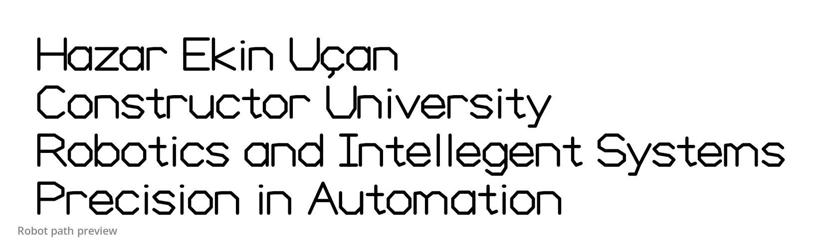
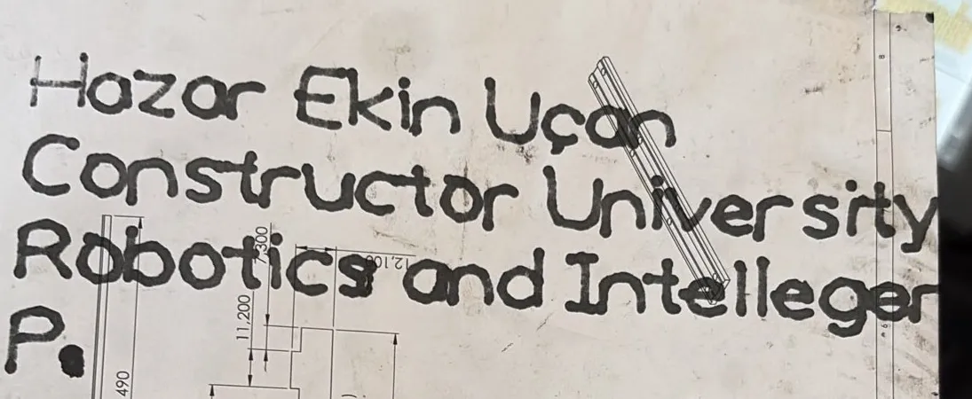
Below is the robot writing. There is no audio. The original recording is workshop noise and carries nothing.
The FANUC 200iD/7L drawing the second line, pen in contact, paper taped to the table. Filmed on a phone at the end of the internship. No audio.
The project pulled in nearly everything I had learned in the previous weeks. Teach pendant operation, tool and user frames, registers and position registers, digital I/O, motion types and speeds, mastering, calibration and alarm troubleshooting all ended up in it. At the end there was something I could look at and tell straight away whether it worked.
Where the limits are
I did not measure anything. There is no repeatability figure, no line width consistency measurement and no cycle time, because I did not take them. The test was whether the text came out legible, and it did. I sized the spring by trying springs, not by calculation. If I built this again I would put a dial indicator on the plate and characterise the compliance properly, and I would log the commanded Z against the achieved Z so the calibration error had a number attached to it instead of a feel.
Evidence on this page: Demo video · Source code · Generated output